MWR (Envisat) Overview
Applications

Data from the Envisat Microwave Radiometer (MWR) was used in the tropospheric path correction of the radar altimeter signal, which was affected both by atmospheric water vapour and by liquid water.
The microwave radiometer was an integral part of the altimetric system on board Envisat, contributing brightness temperature from both channels, water vapour, liquid water and tropospheric path delay data to radar altimetry products.
In addition, the microwave radiometer data could be used in the study of Ice characteristics, snow cover, Surface radiation and the surface energy budget, Soil moisture over land.
Design

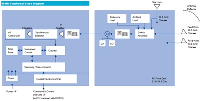
The MWR instrument on board Envisat was a dual channel, nadir pointing Dicke type radiometer, operating at frequencies of 23.8 GHz and 36.5 GHz.
In order to eliminate Earth's irradiation, differential measurements at two frequencies had to be performed. The optimal frequency setting was achieved by using one frequency at the maximum and one at minimum attenuation. The frequencies 23.8 GHz ad 36.5 GHz were the result of a trade off between instrument (reflector) size required to cover a horizontal area on the Earth surface comparable to the RA-2 beam and the maximum sensitivity to water vapour change in the atmosphere.
With one feed horn for each frequency, the MWR pointed via an offset reflector at an angle close to nadir. The instrument configuration was chosen such that the 23.8 GHz channel was pointing in the forward direction, the 36.5 GHz channel in the backward direction with a footprint of about 20 km diameter for each beam.

The MWR instrument design principle was based on the design for the ERS-1 instrument. In nominal Dicke operation, the measured antenna temperatures were continuously compared with an internal reference load at a known temperature. In instrument internal calibration mode, the receiver was either connected to a sky horn pointing to cold space (cold reference) or to a load at ambient temperature (hot reference). The calibration range thus covered was 3 K to 300 K with a reference temperature accuracy of better than 0.1 K. Instrument internal calibration was performed every few minutes.
The microwave radiation was received by an offset feed parabolic reflector antenna, routed through a Dicke switch assembly to a down converter which translated the K- and Ka-band signals to a suitable IF range. The IF signal was passed through a band limited amplifier to a synchronous detector. The detected signal was integrated, sampled and the resulting level converted to a corresponding frequency which was measured. These measurement data, reference load temperatures and ancillary data were routed to the MWR/DORIS ICU for further transmission.
Retrieval of antenna and brightness temperature values from measurement data was accomplished by ground processing. This considered ground calibration data, antenna characteristics and in-orbit characterisation data.
On Envisat, the design of the MWR had to be modified in some areas compared to its ERS-1/2 predecessor to comply with the different platform and mission requirements. The structure was a new design using CFRP technology having the old deployable antenna replaced by a non-deployable one, fully integrated into the instrument structure.

The design of the Central Electronics had been adapted to the revised internal and external interface requirements and to the change of components. The Local Oscillators featured a completely new design where the Gunn Oscillators had been replaced by Dielectric Resonator Oscillators.
Technical Specifications
- Accuracy: 2.6K
- Spatial Resolution: 20 km
- Swath Width: 20 km
- Waveband: Microwave: 23.8 and 36.5GHz
Mission Operations
Download the list of events that affected the MWR instrument during the Envisat lifetime.