ASAR Overview
Applications
ASAR had applications across the disciplines of ocean and coastal data, land, natural disasters and snow and ice.
Design
The Concept of ASAR
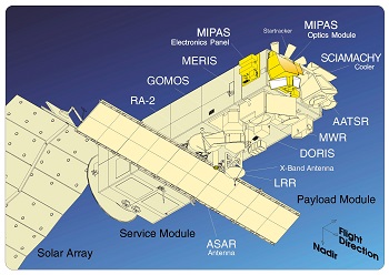
The ASAR instrument consisted of a coherent, active phased array Synthetic Aperture Radar (SAR) - i.e., with distributed transmitter and receiver elements. It was mounted with the long axis of the antenna aligned with the satellite's flight direction (i.e., the Y-axis or azimuth direction). The SAR antenna, with its two-dimensional beam pattern, was able to image a strip of ground to the right side of the flight path, which had unlimited content in the direction of motion (i.e., the Y-axis) but was restricted in the orthogonal direction (i.e., the range direction) by the antenna elevation beamwidth. The objective of the SAR system was to produce a two-dimensional representation of the scene reflectivity at a high resolution, with axes defined in the range and azimuth direction.
The range resolution of a pulsed radar system is limited fundamentally by the bandwidth of the transmitted pulse (i.e. the wider the bandwidth, the better the range resolution). A wide bandwidth could be achieved by a short duration pulse. However, the shorter the pulse, the lower the transmitted energy, for a fixed-peak power limitation, and the poorer the signal to noise ratio (SNR), and hence the radiometric resolution. To preserve the radiometric resolution, the technique adopted by ASAR was to generate a long pulse with a linear frequency modulation (or chirp). The length of the pulse was consistent with the requirement for the SNR. The chirp bandwidth was defined by the required range resolution. After the received signal had been compressed, the range resolution was optimised without loss of radiometric resolution.
The azimuth resolution of a real aperture radar system is a function of the antenna length (i.e. the larger the antenna, the better the azimuth resolution). It is known that a spaceborne real aperture radar giving a useful azimuth resolution for points on Earth's surface would require an impractically large antenna. Aperture synthesis, therefore, offers a means of greatly improving the azimuth resolution.
The measurement principles of ASAR depend on the use of coherent radiation, together with precise knowledge of the transmit and receive point of the radar pulse. For a given target, as the platform moves, the distance from the radar to the target (i.e., the slant range) changes continuously, hence the phase of the reflected signal changes according to a law given by the geometry of observation. As this law is deterministic, it is therefore possible to correctly phase the return signals with respect to each other so that the net effect is equivalent to them all having been received simultaneously by an antenna of length equal to the path length over which the radar signals are collected (i.e. the synthetic aperture). In this way, the synthesised antenna could be thought of as a number of independently radiating elements (i.e. the real aperture), whose separation is established by the pulse repetition frequency (PRF) and the platform velocity.
The change of the phase with respect to time is the Doppler angular frequency. The azimuth resolution is determined by the Doppler bandwidth of the received signal. For ASAR, the bandwidth of target returns, in azimuth, was defined by the Doppler bandwidth covered between the half-power points of the one-way azimuth pattern. This implies that pulses must be transmitted with a repetition frequency greater than the azimuth bandwidth in order to satisfy the Nyquist sampling criterion.
There is an upper limit on the PRF, imposed by the geometry. If the PRF is so high that return signals from two consecutively transmitted pulses arrived simultaneously at the receiver, there would be ambiguities in the response. This would therefore have defined a set of unambiguous intervals for a given geometry and PRF, which correspond to constraining the ground range extent of the region illuminated within the elevation beamwidth of the antenna footprint (i.e. the swath width).
As a consequence of the ASAR antenna being used for pulse transmission and echo reception, there would be echoes that were not received due to periods when the antenna was transmitting pulses and hence not receiving echo returns. For a given geometry and PRF, these 'blind' intervals lay at constant ground range positions.
The returns from nadir (the ground point vertically below the satellite) were significantly larger than the returns from the required swath, because of its close range and high reflectivity. To avoid this unwanted signal saturating any other returns arriving at the same time, the PRFs for ASAR were chosen such that the nadir returns did not occur in the imaging window.
The significant feature of the ASAR instrument was the active phase array antenna, which allowed independent control of the phase and amplitude of the transmitted radiators from different regions of the antenna surface. It also provided independent weighting of the received signal to each of these regions. This offered great flexibility in the generation and control of the radar beam, giving the ASAR instrument the capability to operate in a number of different modes. These modes used two principal methods of taking measurements; the ASAR instrument could operate as a conventional stripmap SAR or as a ScanSAR.
Characteristics
ASAR measured the radar backscatter of the Earth's surface at C-band with a choice of five polarisation modes: VV, HH, VV/HH, HV/HH, or VH/VV, where V is vertical and H is horizontal. This enhanced capability was provided by significant differences in the instrument design: a full active array antenna equipped with distributed transmit/receive modules that provided distinct transmit and receive beams, a digital waveform generation for pulse "chirp" generation, a block adaptive quantisation scheme, and a ScanSAR mode of operation by beam scanning in elevation.
Compared to ERS AMI, ASAR was a significantly advanced instrument employing a number of new technological developments, which allowed extended performance. The most challenging development was the replacement of the centralised high-power amplifier combined with the passive waveguide slot array antenna of the AMI by an active phased array antenna system using distributed elements. The resulting improvements in image and wave mode beam elevation steerage allowed the selection of different swaths, providing a swath coverage of over 400 km wide using ScanSAR techniques.
The ASAR instrument was a phased array radar with 320 Transmit/Receive (T/R) modules arranged across the antenna, such that by adjusting individual module phase and gain, the transmit and receive beams could be steered and configured.
The instrument comprised of two major functional groups: the antenna subassembly (ASA) and the central electronics subassembly (CESA) with subsystems. The active antenna contained 20 tiles with 16 T/R modules each. The ASAR instrument was controlled by its instrument control equipment (ICE), which provided the command and control interface to the satellite. Macro-commands were transferred from the payload management computer to the ICE where they were expanded and queued. The ICE maintained and managed a database of operation parameters, such as transmit pulse and beam characteristics for each swath of each mode, and timing characteristics, such as PRFs and window timings. The ICE downloaded parameters from the database during transition to the operation mode. The ICE provided the operational control of the ASAR equipment, including the control of power and telemetry monitoring.
The transmit pulse characteristics were set within the data subsystem by coefficients in a digital chirp generator which supplies in-phase (I) and quadrature (Q) components. The output of the data subsystem was a composite up-chirp centred at the Intermediate Frequency (IF) carrier.
The signal was then passed to the Radio Frequency (RF) subsystem where it was mixed with the local oscillator frequency to generate the RF signal centred on 5.331 GHz. The up-converted signal was routed via the calibration/switch equipment to the antenna signal feed waveguide. At the antenna, the signal was distributed by the RF panel feed waveguide network to the tile subsystems. The T/R modules applied phase and gain changes to the signal in accordance with the beam forming characteristics that had been given by the tile control interface unit (TCIU), taking into account compensation for temperature effects within the T/R modules. The signal was then power amplified and passed via one of two feeds (V or H) to the tile radiator panel.
Echo signals were received through the same antenna array and passed to the T/R modules for low noise amplification, and phase and gain changes, which determined the receive beam shape. The outputs from each module were routed at RF via the corporate feed and antenna RF distribution system, which acted as a combiner, effectively adding signal inputs coherently and noise inputs incoherently.
Coherent RF/IF conversion of the RF echo signals was performed in the downconverter. I/Q detection of the IF echo signal was accomplished in the demodulator of the data subsystem. The resulting baseband I/Q signals were further processed in the data equipment, which performs filtering, digitalisation, and compression of this data. After buffering and packetising, the echo data was transmitted to the measurement data interface.
The power conditioning unit (PCU) provided a regulated supply to the data subsystem, the RF subsystem and auxiliary power to the antenna power switching and monitoring unit.
Sensor Modes
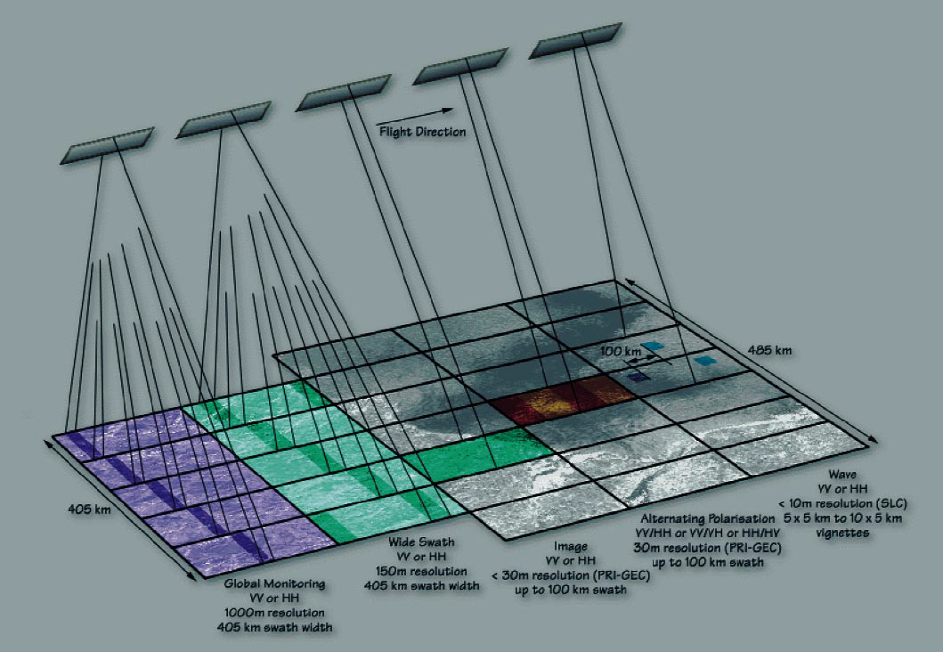
ASAR has five mutually exclusive modes of operation
Global Monitoring Mode (GM)
The Global Monitoring Mode provided low resolution images (1 km) using ScanSAR technique over a 405 km swath at HH or VV polarisation. The mode had a low data data rate due to a slightly reduced along-track duty ratio and the use of digital filtering for reduction in the across-track direction. The same subswaths as defined for the Wide Swath Mode were used.
Wave Mode (WM)
In Wave Mode, the ASAR instrument, measured changes in backscatter from the sea surface due to ocean wave action. Therefore, it generated vignettes, minimum size of 5 km x 5 km, similar to ERS AMI wave mode, spaced 100 km along-track in HH or VV polarisation. The position of the wave vignette across track were selected as either constant or alternating between two across-track positions over the full swath range.
Examples of simulated ASAR wave mode spectra:
- Simulated ASAR cross-spectra versus buoy measurements
- Comparison of real part of ERS and ASAR - Respective spectra
- Comparison of complete ERS and ASAR - Cross spectra
- Comparison of complete ERS and ASAR - Wave mode spectra
Image Mode (IM)
In Image Mode the ASAR generated high spatial resolution products (30 m) similar to the ERS SAR instrument. It imaged one of the seven swaths located over a range of incidence angles spanning from 15 to 45 degrees in HH or VV polarisation. In the table below the range of the values is due to the different orbit positions. The values are given for Level 1b products.
| ASAR Swathes | Swath Width [km] | Near Range Incidence Angle | Far Range Incidence Angle |
|---|---|---|---|
| IS1 | 108.4 - 109.0 | 14.1 - 14.4 | 22.2 - 22.3 |
| IS2 | 107.1 - 107.7 | 18.4 - 18.7 | 26.1 - 26.2 |
| IS3 | 83.9 - 84.3 | 25.6 - 25.9 | 31.1 - 31.3 |
| IS4 | 90.1 - 90.6 | 30.6 - 30.9 | 36.1 - 36.2 |
| IS5 | 65.7 - 66.0 | 35.5 - 35.8 | 39.2 - 39.4 |
| IS6 | 72.3 - 72.7 | 38.8 - 39.1 | 42.6 - 42.8 |
| IS7 | 57.8 - 58.0 | 42.2 - 42.6 | 45.1 - 45.3 |
Alternating Polarisation Mode (AP)
Alternating Polarisation Mode provided high resolution products in any swath as in Image Mode but with polarisation changing from subaperture to subaperture within the synthetic aperture. Effectively a ScanSAR technique was used but without varying the subswath. The results were in two images of the same scene in different polarisations combination (HH/VV or HH/HV or VV/VH) with approximately 30 m resolution (except IS1). Radiometric resolution was reduced compared to Image Mode.
Wide Swath Mode (WS)
In the Wide Swath Mode the ScanSAR technique was used, providing images of a wider strip (405 km) with medium resolution (150 m) in HH or VV polarisation. The total swath consisted of five subswaths and the ASAR transmits bursts of pulses to each of the subswaths in turn in such a way that a continuous along-track image was build up for each subswath.
- Accuracy: Radiometric resolution in range: 1.5-3.5 dB, Radiometric accuracy: 0.65 dB
- Spatial Resolution: Image, Wave and Alternating Polarisation modes: approx 30m x 30m.Wide Swath mode: aprox 150m x 150m. Global Monitoring mode: aprox1000m x 1000m.
- Swath Width: Image and alternating polarisation modes: up to 100km, Wave mode:5km, Wide swath and global monitoring modes: 400km or more
- Waveband: Microwave: C-band, with choice of 5 polarisation modes (VV, HH, VV/HH, HV/HH, or VH/VV)
Mission Operations
As ASAR was a very successful mission, there were many highlights. Standard ASAR operations provided a 35 day repeat orbit. Major events during operations included:
ASAR Data Subsystem Redundancy Switch (May 2003)
First signs of an on-board anomaly were found with the quality of ASAR data just after launch, although no problems were detected from the instrument telemetry. A failure was then found on the Q-branch of the on-board transmitter. ASAR was switched of on 14 May 2003 to change the data subsystem (DSS) from side A to side B. Following the switch to DSS-B ASAR operations resumed on 2 June 2003 with nominal data quality.
ASAR Antenna Reset #1 (September 2005)
A drift in the gain and phase of most Transmit and Receive Modules (TRMs) was seen from the start of the mission. Due to the accumulated gain and phase drift for a large percentage of the TRMs, the first of two antenna resets was performed on the 14th and 16th September 2005 in order to correct, as far as possible, the TRM drift.
ASAR Wide-Swath Burst Synchronisation (September 2006)
To perform interferometry with ASAR WS imagery, it is necessary for there to be an overlap in the bursts (in the azimuth direction) in the pair of products in each of the sub-swaths, otherwise it is not possible to generate an interferogram (since there will be no correlation between the pair of products as the same point on the ground would be imaged by a different part of the azimuth beam). The acquisition start times for ASAR WSM imagery were altered in September 2006 so that it started at discrete points around the orbit to maximise the chances of burst overlap between pairs of products. The revised planning strategy became operational from 17 September 2006 (orbit number 23783). Rosich et al. (2007) provide details of the Burst Synchronisation optimisation.
Recalibration of IM and AP modes (January 2007)
Following the successful re-deployment of three ASAR transponder from The Netherlands to Kalimantan (Indonesia), Resolute (Canada) and Ottawa (Canada) since mid-2006, many more transponder measurements have been made. This made it possible to perform a detailed analyses of the ASAR transponder relative radar cross-section (rcs) as a function of product type, swath and polarisation. This analysis showed the necessity of performing a re-calibration of IM and AP products via the generation of revised calibration constants. The radiometric re-calibration of ASAR Image and Alternating Polarisation modes was performed in December 2006 and January 2007 and is applicable for all products acquired since the start of the ASAR mission.
ASAR AP Swath Modifications (May 2009)
Unplanned shut-downs of the ASAR instrument had been occurring when acquiring alternating polarisation (AP) data since launch. Unplanned shut-downs are undesirable due to the possible degradation of the instrument hardware. The number of AP acquisitions was reduced significantly in early 2007 while the usage of instrument swath 5 (IS5) was suspended at the end of 2006, both to reduce the occurrence of these unplanned shut-downs. Changes were made to the Envisat ASAR AP swath characteristics at the end of May 2009 to reduce the number of shut-downs, thus enabling the resumption of AP IS5 data acquisitions and the increased usage of all other AP swaths. Details of the swath modifications are available.
ASAR Antenna Reset #2 (March 2010)
The decision to perform a second ASAR antenna reset activity during early 2010 was based on the gain and phase drifts that has occurred over the previous 4+ years for each of the 320 antenna TRMs (i.e. to bring the gain and phases close to pre-launch values). The upload of the files containing the required corrections took place as planned starting at 09:44 UT on 11 March 2010 during orbits 41974, 41975 and 41976, with a further upload on 17 March 2010 at 12:04:10 UT. Improvements were seen in all gains and phases after the reset, with values being relative to the start of the mission.
Envisat Orbit Change (October 2010)
In order the extend the Envisat mission beyond its nominal lifetime of 5 years and due to limited fuel remaining on-board (required for orbit manoeuvres and attitude control), it was decided to reduce the orbit altitude and cease some of the inclination orbit manoeuvres. The reduction in altitude was also the first step in placing Envisat in its end of life orbit. From 22 October 2010 the altitude of the orbit was reduced by about 17.4 km to 782.39 km. The Orbit Lowering Manoeuvre was completed on 2 Nov 2010 and the mission extension phase was entered.
Tandem Missions
Tandem missions, joint interferometric modes with ERS-2 and Envisat SAR instruments, occurred four times throughout Envisat's lifetime.
- The first Envisat/ERS-2 SAR tandem mission took place from September 2007 to 14 February 14 2008.
- The second Envisat/ERS-2 SAR tandem mission started on 23 November 2008 and ended in late April 2009 (both spacecraft acquired data over the same area just 28 minutes apart). The second campaign was due to end in late January 2009, but was extended through to late April 2009 due to the excellent performance of the satellites and the strong teamwork between the mission data teams at ESRIN and ESOC.
- The third tandem campaign occurred from 14 February 2010 to 26 April 2010.
- The fourth tandem campaign, from 6 July 2010 to 22 October 2010, focused on low-lying coastal areas, such as New Orleans in USA and the Po River Mouth in Italy.
Leap Frog Mode
From 26 November 2010 to 9 December 2010 an experimental Leap Frog mode was used, whereby the swath used from one wave mode imagette to another was switched between IS2 and IS4. This was repeated from 25 May 2011 to 6 June 2011, again alternating from IS2 and IS4. The polarisation remained constant, set to HH in a first step (2 weeks) and will move to VV for the remaining 2 weeks.
General operation concept
All instruments on Envisat, with the exceptions of the ASAR imaging modes and of the MERIS full-resolution mode, were operated as part of the global mission. The global mission operation strategy was intended to provide the maximum coverage of the Earth components (atmosphere, ocean, ice, land) relevant to each payload instrument. This was based on:
- continuous operation of the low-rate instruments around the orbit (with the exception of MERIS, which is limited by sun-illumination conditions);
- on-board recording of all instrument data;
- data-recorder playback at least once per orbit in order to ensure availability of fast delivery products within less than three hours from observation
- systematic processing of all acquired data.
A nominal data recovery scenario was defined, when both Artemis and the on-board recorders are available, which ensures the recovery of the full low-rate global data set. The dumping of the recorders was equally shared (seven consecutive orbits each) between the Kiruna X-band payload data handling station and the Ka-band Artemis user Earth terminal attached to the ESRIN payload data handling station. Backup scenarios were defined in case of temporary or permanent unavailability of Artemis, which made optimal use of on-board recorders and of the ESA ground segment.
Processing and data distribution strategy
Low-rate data was systematically processed on the ground and disseminated to users in near real time (NRT). NRT users registered as "subscribing" users for the systematic reception of these products. All data was reprocessed off-line. Nominal off-line distribution was performed on physical media to registered users. Small products was available for retrieval on line, with the possibility for users to extract partial data sets.
Regional mission operations and data recovery strategy
The regional mission includes the full-resolution mode of MERIS and all modes of the ASAR, with the exception of the wave mode. The following sections provide the basic concepts ruling the operations of the regional mission.
ASAR general operation strategy
ASAR offered, by exploiting the combinations of polarisations and incidence angles, 37 different and mutually exclusive operating modes in high-, medium- (wide swath mode), and reduced- (global monitoring mode) resolution. These modes were operated mainly in response to user requests. Wave mode was also mutually exclusive with respect to all the other modes. It was a low-rate mode operated systematically over oceans as part of the global mission.
Global monitoring and wave modes were recorded systematically when operated. ASAR high- and medium-resolution imaging modes were either transmitted on a real time link (direct X-band or via Artemis Ka-band link) or recorded on the on-board solid state recorder for ground data recovery. The high- and medium-resolution data were acquired only when required to satisfy either a background mission scenario and/or user requests.
ASAR processing and data distribution
All ASAR high-rate data acquired by ESA facilities was systematically processed in near real time to generate medium-resolution products (around 150 m resolution) and browse products. Browse products were available on-line. High-resolution products were processed in near real time or off-line, upon user request. All medium- and high- resolution products were delivered to users on request either in near real time on a dissemination channel or off line on physical media.
Regional mission data recovery
For operation and data recovery of ASAR high- and medium-resolution data the following nominal strategy was applied:
- data over Europe will be acquired directly via X-band links (Kiruna and Matera coverage),
- data outside Europe will be acquired whenever possible via Artemis direct transmission to the UET located at ESRIN,
- data outside direct coverage of the ESA X-band stations and Artemis, was recorded on board using the SSR and acquired via deferred dump to one of the ESA stations via X- or Ka-band links,
- data requested by a station operator or by the distributing entities on behalf of a station operator was transmitted in X-band for acquisition by the corresponding station,
- if data to be acquired by a station operator was also needed as part of ESA archive, then in parallel with X-band direct data transmission, ESA acquired the data via combined use of the SSR, X- or Ka-links as appropriate.
In case of unavailability of Artemis, whether temporary or permanent, the regional mission data acquisition was not affected. The time required to recover the data could restrict in some orbits the provision of three hour NRT services, but would still preserve potential delivery of products to users within less than a day for data acquired over any site in the world.